I am one of the people who ordered themselves a „WiFi modem“ for the C64/C128 user port, so that the old 8-bit computer is no longer lonely and can join the modern Internet. It took me a while to understand how these „WiFi modems“ and the Internet connection itself work, despite the information already available on the Net. In short, the WiFi device
- Can talk with the Commodore computer thru a serial interface
- Can connect to the local network via WiFi
- Can connect the Commodore computer to the Internet via a router
- Can transform the Commodore computer into a network client
- Can transform the Commodore computer into a network server
This article attempts to explain what above assembly exactly is and how the network connection works, baby step by baby step. I am not explaining things like setting up your WiFi, as there are enough good articles and YouTube videos for that out there.
STRIKELINK WIFI ADAPTER
Let´s start with the product I purchased off eBay: a „Strikelink WiFi Modem“. To be fair, the entry on eBay said „Commodore 64 / 128 WiFi Modem / WLAN Adapter STRIKELINK“. Why is this important? Everybody who remembers modems knows that these were typically small external devices that connected to the computer thru a serial connection (following the UART/RS-232 standard) on one side and to a carrier (phone) network on the other. The modem is a modulator/demodulator between analog (phone) and digital (computer) signals, hence its name. The little thingy I got from eBay is digital on both sides, so a better term than modem would be „adapter“, which I will use from now on.
By the way, there are more WiFi adapters for the C64/C128 available, but I will focus on the one from Strikelink „by Alwyz“. Other devices usually use the same or similar architecture. In my case, I received just the Strikelink WiFi assembly as is, other sellers offer a 3D printed case for the assembly in addition.
Site note: The name "Strikelink" came from an old terminal program called "Striketerm" in 2014, created by the same author as Strikelink and based on the Novaterm terminal program. 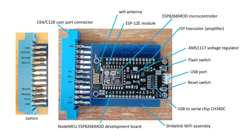
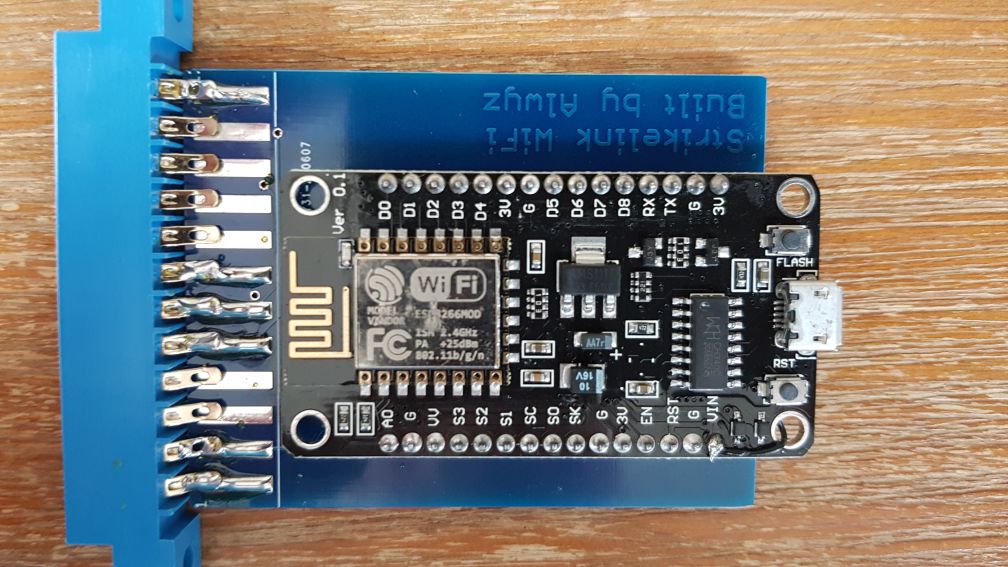
The adapter consists off a 32-bit microprocessor called L106 32-bit micro controller unit (MCU) from company Tensilica at the core of the assembly. The MCU is packaged into a system-on-a-chip (SoC) from Chinese company Espressif Systems called ESP8266. The chip includes the CPU (MCU), boot ROM, flash RAM, a TCP/IP stack, and an IEEE 802.11b/g/n WiFi interface in one single package. Current version of the SoC is called ESP8266EX. The chip sits on top of a module carrier called ESP-12E that adds a 20 dBm WiFi antenna. This module in turn is fixed to an inexpensive development board called the NodeMCU ESP8266MOD. My board has version 0.1. The board adds a micro USB port, a voltage regulator for the USB port, a USB to serial converter, two small switches, a blue activity LED, GPIO pins, other discrete components, and four holes for standoffs. Last but not least the development board is fixed to a blue printed circuit board that has a C64/C128 user port connector attached on one side. This assembly is now called the Strikelink WiFi adapter. Anybody confused now?
Side note: There is also a development board called "NodeMCU Amica Modul V2 ESP8266 ESP-12F" with the CP2102 USB to serial converter and a "NodeMCU Lolin V3 Module ESP8266 ESP-12F" (Version 0.1) with the CH340 USB to serial converter, as shown in the picture above. These boards are interchangeable with the one I am using. The "LOLIN D1 Mini V 4.0.0" and "LOLIN D1 Mini Pro V 2.0.0" boards are based on the ESP8266 SoC but have different connectors and pinouts. There was also a batch of Strikelink WiFi adapters with a green PCB and the CP2102 chip. These were made by a user called Retro4all. Another variant of the past is the "C64Net Wifi Card" from Electronics Is Fun by the well-known Bo Zimmerman. This WiFi adapter uses different AT commands as shown later on in this article as well as a different firmware.The ESP8266 SoC can be programmed using the USB port with i.e. the Arduino IDE. In the case of the NodeMCU version, the firmware is based on the scripting language Lua and development is done via the Espressif Non-OS SDK for ESP8266. The SPIFFS file system is being supported, on which Lua scripts are being executed by the CPU. A Lua script could start a small Web server, for example.
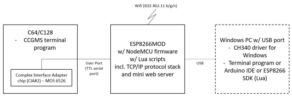
The above picture gives a functional view on the complete setup, from the C64/C128 computer on the left to an optional development PC on the right. I will not address the development PC any further in this article, as it is not needed for the connection to the Internet. Missing in this picture is a Windows PC (192.168.1.53), which I used to test the network connection with the Commodore computer.
THE SERIAL CONNECTION BETWEEN THE COMMODORE AND THE WIFI ADAPTER
The connection between C64/C128 and the WiFi adapter is a serial connection based on the Commodore user port standard – not the more common RS-232 standard. The computers transmit line (TX) and the receive line (RX) are operated on „TTL levels“, meaning that the signal alternates between 0 and 5V DC, not the common RS-232 levels.
Side note: The Commodore C64 and C128 do not have a chip that can provide RS-232 for cost reduction reasons. Instead, the second of the two MOS 6526 chips (both called CIA, Complex Interface Adapter) has to somehow substitute the RS-232 functionality that a chip like the MOS 6551 in the Commodore PET can deliver. Read more about this at https://www.pagetable.com/?p=1656.The good news is that our WiFi adapter is fine with that. In order to set up a communication between Commodore computer and adapter, certain UART (Universal Asynchronous Receiver Transmitter) basic parameters must be set the same on both sides, namely the transfer speed („baud rate“), the use of parity and stop bits, the packet (data) length, parity bit, and the duplex mode. See chapter „RS-232: Mock 6551 Command Register“ (memory address 660/$294) in „Mapping the C64“ for a detailed explanation on these settings. BTW, a must have book for all of us. We will start with 2400 baud, 8 data bits, one stop bit, odd parity, full duplex. But how to do this? This is why we need a „terminal program“, a software that can set the parameters for the serial connection of the C64/C128 but also for the WiFi adapter. The recommended terminal program for the C64/C128 is called „CCGMS“ and can be found on the Internet.
Side note: In RS-232 speak, the Commodore computer´s serial interface becomes the Data Terminal Equipment (DTE), the WiFi adapter´s serial interface the Data Communications Equipment (DCE). The DTE generates the data (like from our input on the keyboard into a terminal program) and hands it over to the DCE for transmission (on the WiFi network). In case we connect to an Internet server, this server is also a DTE that generates data the Commodore computer wants to receive. To be more precise: the local DTE generates a data packet on the serial line, hands it over to the DCE, which takes the data and stuffs it into an IP packet, which is put on the IP network via the WiFi connection. The local router routes the IP packet towards the remote DTE, typically a server. The server answers the request and the reply travels in the opposite direction.In order to set the serial connection on the C64/C128, CCGMS is mainly using memory addresses $0293 (the control register of CIA chip #2) and $0294 (the command register). The first address is for setting the baud rate, the number of data bits, and the number of stop bits. The second address is for setting the synchronization type, the transmission type, and the parity.
After starting CCGMS, pressing the <F7> key will open up the configuration screen:
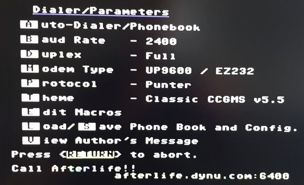
Here the baud rate is set to „2400“, transmission type is set to „Full“, and the modem type is set to „UP9600/EZ232“. <RETURN> closes this screen and returns to the main screen of the terminal program.
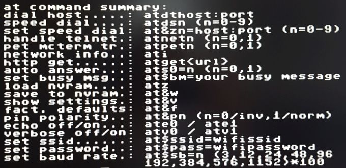
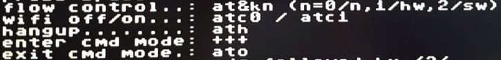
CCGMS can talk with the NodeMCU firmware on the WiFi adapter by sending a subset of the so called Hayes AT commands. These commands can be used to set the baud rate, set the flow control, set the WiFi SSID, set the WiFi password, store the setup, read the current configuration settings, and so on. Using a non supported AT command will result in an „error“ message on the screen. The supported commands are:
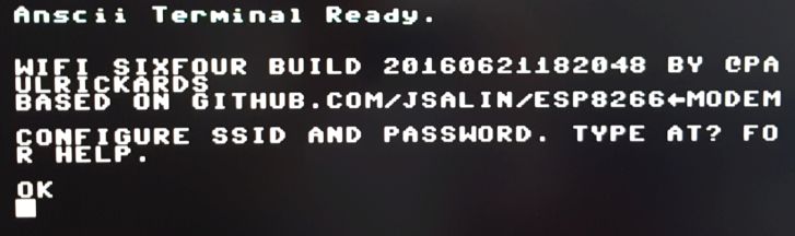
After setting up everything correctly, the WiFi adapter will answer with a welcome message as soon as the user hits the <RETURN> key:
CONNECTING THE WIFI ADAPTER TO THE NETWORK
If the serial connection is working, the adapter must connect to the local WiFi network. The message will look something like
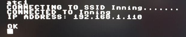
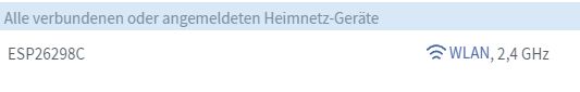
In above example, „Inning“ is the SSID of the WiFi network I am using and „192.168.1.110“ is the IPv4 address the WiFi router´s DHCP server returned to be used by the WiFi adapter. Now the WiFi router will also show the WiFi adapter in its list of devices:
As soon as the WiFi adapter has an IP address, it can be ping’ed from other devices:
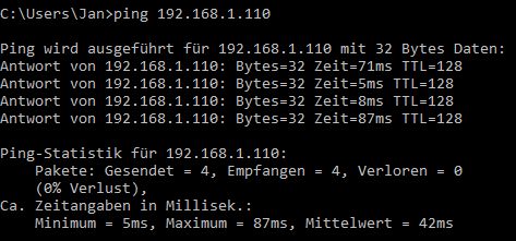
Now the Commodore computer officially joined the local network!
THE COMMODORE COMPUTER AS A SERVER
Another computer can connect to the Commodore computer on TCP port 80. Type in the IP address of your WiFi adapter into the Web browser and you will get a response from the NodeMCU Web server:
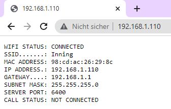
The „CALL STATUS: NOT CONNECTED“ from the Web server means that no client has yet established a connection to the WiFi adapter. The „SERVER PORT: 6400“ tells us that the WiFi adapter itself not only listens to port 80 but also on TCP port 6400. If we use a web browser and type in „192.168.1.110:6400“ in the address (URL) field, the web browser will send a HTTP get request to the WiFi adapter, which in turn answers with „ring“ from the client I was using (192.168.1.53) and a „connect 2400“. 2400 being the baud rate. The WiFi adapter is now in „data mode“ to receive or send data. As the web browser does not send any further data packets, nothing will happen.
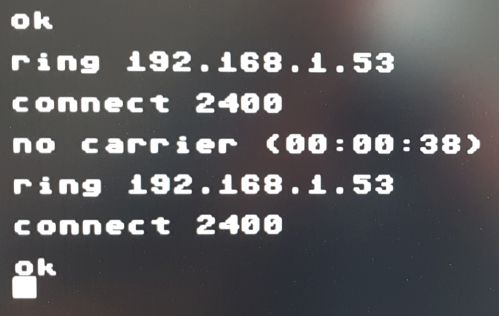
To bring the terminal program back to „command mode“ in which we can enter AT commands, I entered „+++“ and the adapter answered with „no carrier“ plus the time it waited. Now AT commands can be entered again and an „ATH0“ will disconnect the „carrier“.
Next we test the connection to TCP port 6400 of the WiFi adapter using a terminal program like PuTTY from another computer. I set the baud rate to 2400, echo to on (!) and told PuTTY to connect to 192.168.1.110 on port 6400 using the Telnet protocol. The WiFi adapter answers the Telnet request packet from 192.168.1.53 with a „ring“ and a „connect 2400“ message. After that the terminal program displays everything I typed into the PuTTY window:
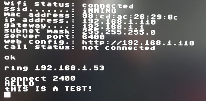
It works the other way too: Whatever we type into the data window of CCGMS will appear in the PuTTY window. This concept of an established terminal connection is important to understand, as it will be used in the BBS example later on. A BBS is nothing but a server „typing“ in text the user will see in the terminal window and will react to.
As soon as the connection is established, the WiFi adapters web server´s response shows a new call status:
WIFI STATUS: CONNECTED
SSID.......: Inning
MAC ADDRESS: 98:cd:ac:26:29:8c
IP ADDRESS.: 192.168.1.110
GATEWAY....: 192.168.1.1
SUBNET MASK: 255.255.255.0
SERVER PORT: 6400
CALL STATUS: CONNECTED TO 192.168.1.53
CALL LENGTH: 00:00:06
The „+++“ will return CCGMS into command mode, „ATH0“ disconnects the carrier and PuTTY answers with „Connection closed by remote host“. In case port 6400 of the WiFi adapter is busy, it will respond with the so called „busy message“ of NodeMCU: „sorry, system is currently busy, please try again later.“. This message can be changed by the user.
Side note: All this happens on OSI layer 3 and above. On OSI layer 2, my WiFi adapter has the MAC address "98:CD:AC:26:29:8C". 98:CD:AC is the vendor code assigned to company Espressif Inc. and 26:29.8C is the individual number of my WiFi adapter.THE COMMODORE COMPUTER AS A CLIENT – CONNECTING TO A BBS
In order to connect to a bulletin board system (BBS), the predecessor of Facebook and Co., we follow these steps:
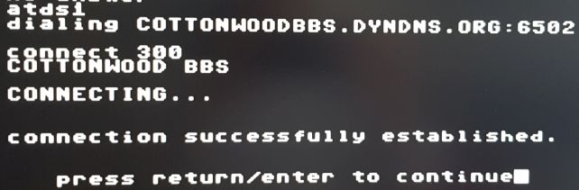
The user enters the command to connect to a server on the Internet in the terminal program, i.e. from the list of speed dial entries by using the command atds1
The adapter receives the command, reads the entries from the speed dial table row 1 („cottonwoodbbs.dyndns.org“, port 6502) and has to query the so called DNS server now to resolve the IP address of the server, meaning it has to map the fully qualified hostname „cottonwoodbbs.dnydns.org“ to its IP address. The DNS server answers with „172.112.142,243“. In a network sniffer, the request/answer data flow looks like

Now the adapter (with the IP address 192.168.1.110 in this example) will connect to the BBS server via its IP address 172.112.142.243, For that a stateful connection is established using the TCP/IP stack of the ESP8266 and picking the TCP protocol. The first three data packets being sent are the three-way handshake. After that the sequence number for the data packets and the window size are negotiated between adapter and server:
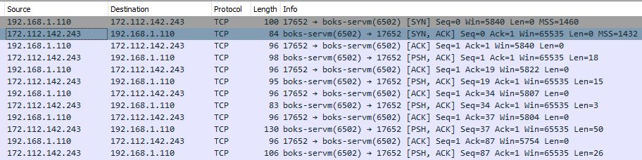
After that (the fourth line in above example) the BBS server starts sending data, in our case the „cottonwood bbs connecting…“ message, followed by the welcome message, as we can see in the terminal window of CCGMS:
The data is a raw US ASCII encoded stream of characters. In contrast to Telnet connections, which start with the IAC (Interpret As Command) byte followed by some special bytes to negotiate Telnet options, the data being sent back and forth between the adapter and the BBS server is simply stuffed into the data portion of the TCP packet. The end of the byte stream is determined by the TCP payload field. If it says i.e. 26 bytes, the TCP/IP stack knows it has to expect 26 data bytes before the next packet. The adapter reads the data bytes and puts them on the serial connection towards our computer. Our terminal program reads the data bytes from the serial interface (from the computers memory, the CIA stored them there) and displays them on the screen. To prevent gibberish to appear on our screen, the US ASCII character must be first translated to the PETSCII we know from Commodore. In our example the very first data byte being sent from the server is 0x63, the character „c“ of „cottonwood bbs“. This is code 0x43 in PETSCII.
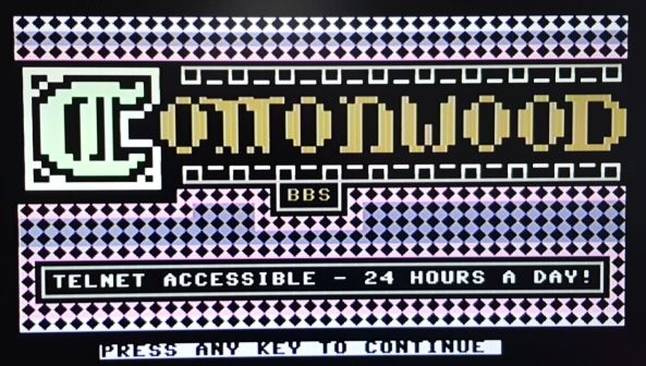
After the log-in procedure the BBS presents its welcome screen and is ready for interaction with the user:
THE COMMODORE COMPUTER AS A WEB CLIENT
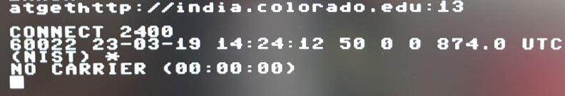
In theory, the Commodore computer can now act as a web client too. The „ATGET“ command typed into the CCGMS terminal window will retrieve a web page from a server:
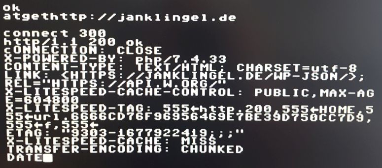
Unfortunately, CCGMS does not know anything about how to render the returned HTML code (which a web browser like EDGE or Chrome does) and displays everything as simple text – not very useful. What can be done instead is query a web server that returns simple text by design, like weather and time servers: